How pressure vessels are inspected during fabrication and in service: stage inspection, radiography, ultrasonic and dye penetrant testing, hydrostatic and pneumatic tests, thickness gauging, relief valves, records and a practical maintenance checklist.

Pressure vessels are inspected at every stage: material check, fit-up, welding, non-destructive testing (radiography, ultrasonic, dye penetrant or magnetic particle), a hydrostatic test at a code-defined pressure above design pressure, final dimensional and documentation review, and then periodic in-service inspection of thickness, corrosion, welds, nozzles and safety devices.
A pressure vessel stores energy. If it fails, the release can injure people, damage plant and stop production. Inspection is how owners and fabricators confirm that a vessel was built as designed and remains safe to operate. Inspection happens in two phases: during fabrication, when the manufacturer and an authorised inspector check material, welding and testing; and in service, when the owner checks for corrosion, cracking, leaks and wear at planned intervals. Both phases rely on records, so that anyone can trace what was checked, by whom and with what result.
The rules that apply depend on the vessel. Vessels built to ASME Section VIII follow code requirements for examination and testing, while boiler and steam-related items in India fall under the Indian Boiler Regulations (IBR). Always follow the code and statutory rules named in your purchase order and local regulations. Creative Engineering holds ASME U and R stamps, NB registration and IBR approval, which support code-compliant fabrication; see our certifications.
| Stage | What is checked | Typical record |
|---|---|---|
| Material receipt | Plate, pipe, forging and fitting against mill test certificates; heat number traceability | Material test certificate, identification marks |
| Marking and cutting | Heat numbers transferred, dimensions and edge preparation | Cutting list, marking record |
| Fit-up | Alignment, root gap, weld joint geometry, nozzle orientation | Fit-up inspection report |
| Welding | Welding procedure and welder qualification, parameters, consumables | WPS, PQR, welder qualification record, weld map |
| NDT | Radiography, UT, PT or MT as required by the design code and joint category | NDT reports and films or digital images |
| Heat treatment (if required) | Stress relief temperature and soak time | Heat treatment chart |
| Pressure test | Hydrostatic or pneumatic test, leak check, pressure holding | Pressure test certificate |
| Final inspection | Dimensions, nozzle details, nameplate, surface condition, documents | Final inspection report, data book |

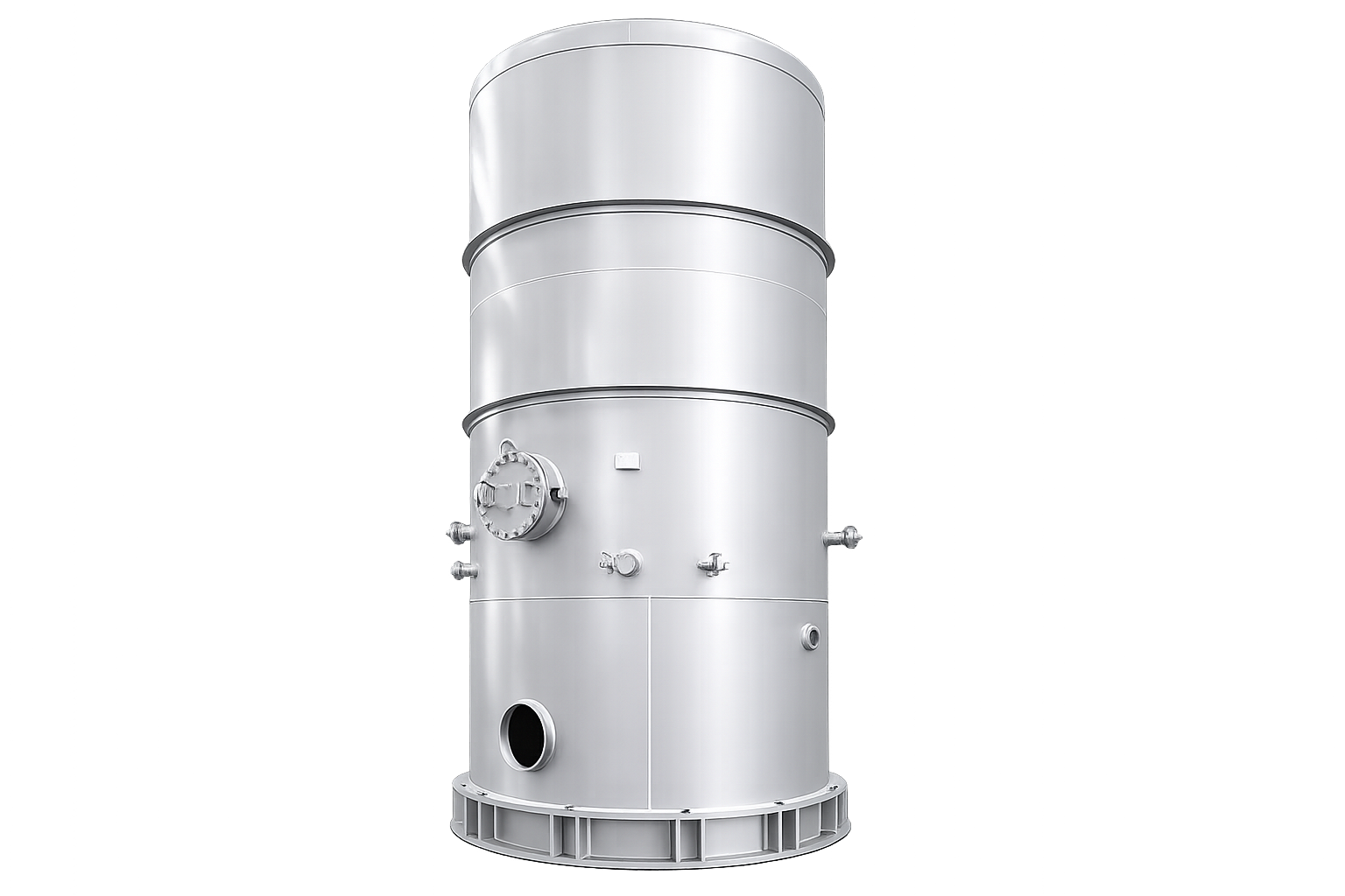
NDT examines welds and materials without damaging them. The methods most used on pressure vessels are:
| Method | Finds | Notes |
|---|---|---|
| Radiographic testing (RT) | Internal weld flaws such as porosity, slag and lack of fusion | Gamma or X-ray film or digital image; required extent depends on code and joint efficiency |
| Ultrasonic testing (UT) | Internal flaws and plate lamination; also thickness measurement | Portable and useful both in fabrication and in service |
| Dye penetrant testing (PT) | Surface-breaking cracks and pores | Common for stainless steel and non-magnetic alloys |
| Magnetic particle testing (MT) | Surface and near-surface flaws in magnetic materials | Used on carbon steel welds and forgings |
| Positive material identification (PMI) | Alloy grade of material | Confirms SS 304, 316L or alloy as ordered |
The hydrostatic test fills the vessel with water and raises the pressure to a code-defined test pressure, higher than the design pressure, to prove strength and detect leaks. Water is used because it is nearly incompressible, so it stores little energy and a failure is far less dangerous than with gas. The general steps are:
For stainless steel vessels, use water with low chloride content, and drain and dry completely after testing to avoid pitting. The exact test pressure and acceptance rules come from the design code; the figure on the drawing and nameplate governs.
Knowing common defects helps buyers read inspection reports. Typical weld flaws include porosity (gas pockets), slag inclusion (trapped non-metallic material), lack of fusion or lack of penetration (the weld metal did not join fully), undercut (a groove at the weld toe), cracks (the most serious, never acceptable in pressure parts) and excessive reinforcement or misalignment. Codes set acceptance limits for each flaw type and size. A weld that fails is repaired with a qualified procedure and re-examined by the same method until it passes.
Where water cannot be used, for example because the vessel cannot be dried or its foundation cannot carry the weight, a pneumatic test may be allowed by the code. It carries higher risk because compressed gas stores a lot of energy, so codes impose extra precautions, lower test pressure and additional NDT. Other leak tests include vacuum box testing of welds, helium leak testing for very tight service, and soap bubble tests on flanges and small connections. For vessels that run under vacuum, a vacuum hold test checks that pressure rise stays within the limit set by the purchaser.
The interval depends on service severity, material, past corrosion rate and local rules. Many owners follow a risk-based plan, with shorter intervals for aggressive service. Keep every report so trends are visible.
Every pressure vessel must be protected against over-pressure by a pressure relief valve or equivalent device set at or below the maximum allowable working pressure (MAWP). Valves must be sized for the worst credible scenario, such as fire, blocked outlet or runaway reaction, and installed so that the inlet line does not restrict flow. Test and calibrate them at regular intervals and keep tags and certificates. Rupture discs can be used on their own or ahead of a relief valve for corrosive or sticky service. Check that no isolation valve can leave the vessel without protection while it is in use.
If a repair involves welding on a pressure-retaining part, it must follow a qualified procedure and the applicable repair code, and may need re-inspection and re-testing. Creative Engineering can support repair, modification and re-rating; send details via the contact page.
Different services cause different damage, and inspection plans should target the likely mechanism. General corrosion thins the wall evenly and is easy to measure with UT. Pitting forms small, deep holes, often in stainless steel exposed to chlorides. Crevice corrosion starts under gaskets and deposits. Stress corrosion cracking appears in stressed parts exposed to specific environments, such as chlorides with 300-series stainless at higher temperature. Corrosion under insulation hides beneath cladding where moisture is trapped. Erosion occurs where fast or abrasive flow hits internal surfaces, such as at inlet nozzles. Choose material and lining carefully at the design stage; our material selection guide explains the options.
| Mechanism | Where it shows up | How it is found |
|---|---|---|
| General corrosion | Shell and heads in acid or wet service | UT thickness gauging |
| Pitting | Stainless surfaces with chlorides | Visual, PT, UT scanning |
| Crevice corrosion | Under gaskets, supports and deposits | Visual after dismantling, PT |
| Stress corrosion cracking | Welds and bends in stressed stainless parts | PT, UT shear wave |
| Corrosion under insulation | Beneath insulation near nozzles and supports | Strip and inspect, radiography, UT |
| Erosion | Inlet nozzles, impingement plates | UT thickness at the nozzle area |
See our quality policy, and learn about vessel types in our pressure vessel guide and reaction vessel guide.
Ask a fabricator how inspection is organised before you place an order. The right partner will share the quality plan, invite your inspector or a third-party agency to witness key stages, and supply a complete data book at dispatch. Look for in-house NDT capability or an established testing partner, qualified welders, calibrated gauges and a traceable material system. Creative Engineering works with customer and third-party inspectors and provides documentation with each vessel. Our two manufacturing units in Ankleshwar, with 1,75,000 sq ft each, allow stage-wise work to be organised without delays. Learn more on our company page.
Through stage inspection during fabrication, NDT such as radiography, UT and dye penetrant testing, a pressure test, and final documentation review; then through periodic in-service inspection.
A strength and leak test where the vessel is filled with water and pressurised to a code-defined test pressure above design pressure and held while welds and joints are examined.
Water is nearly incompressible, so little energy is stored, making a failure much safer than a gas test.
Radiographic testing uses radiation to image internal flaws, while ultrasonic testing uses sound waves to detect flaws and measure thickness.
It depends on service, corrosion rate, material and local regulations; many owners use risk-based intervals and keep full records.
Maximum allowable working pressure is the highest pressure permitted at the top of the vessel at the stated temperature, and relief devices are set at or below it.
Yes. Share the vessel details and condition and our engineers will advise on repair, modification or re-rating.
An ITP lists every inspection and test step, who performs it, which standard applies and whether it is a hold, witness or review point.
Yes. Customer and third-party inspectors can be invited to witness agreed stages such as fit-up, NDT and the pressure test.
Creative Engineering, Ankleshwar, Gujarat designs and manufactures process equipment to ASME and IBR codes. Share your drawing or process data and our team will respond with a technical offer.






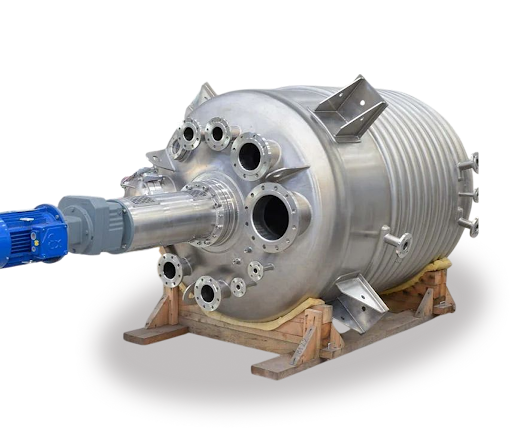 Reactor
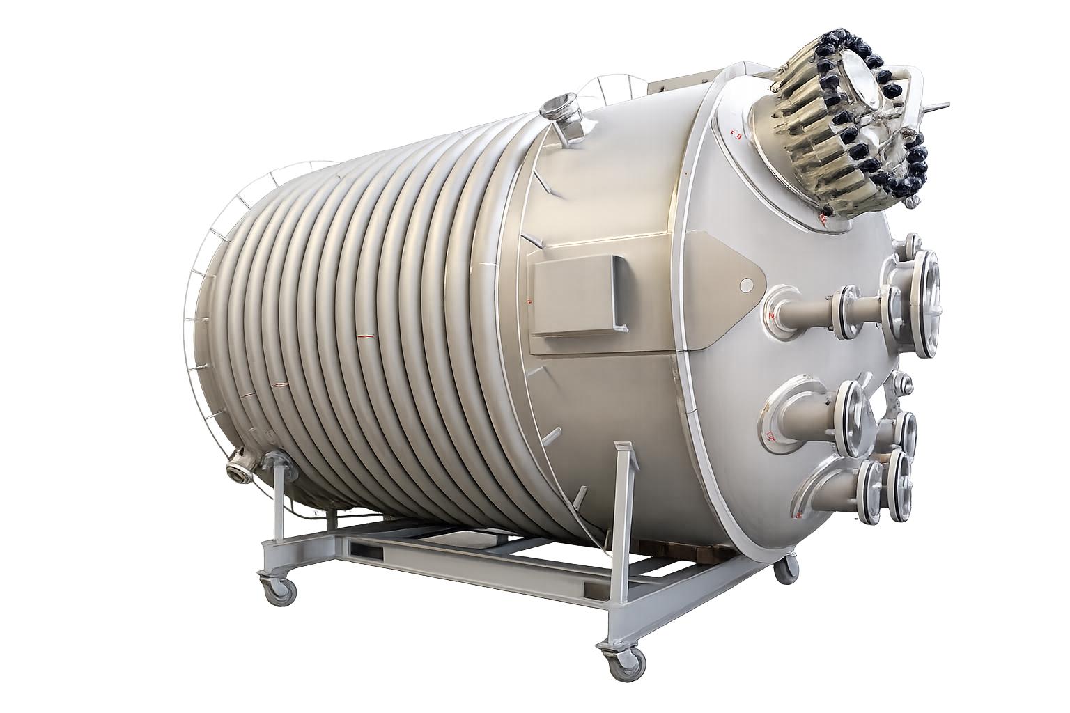 High Pressure Vessel
 Skid Equipment
 Receiver
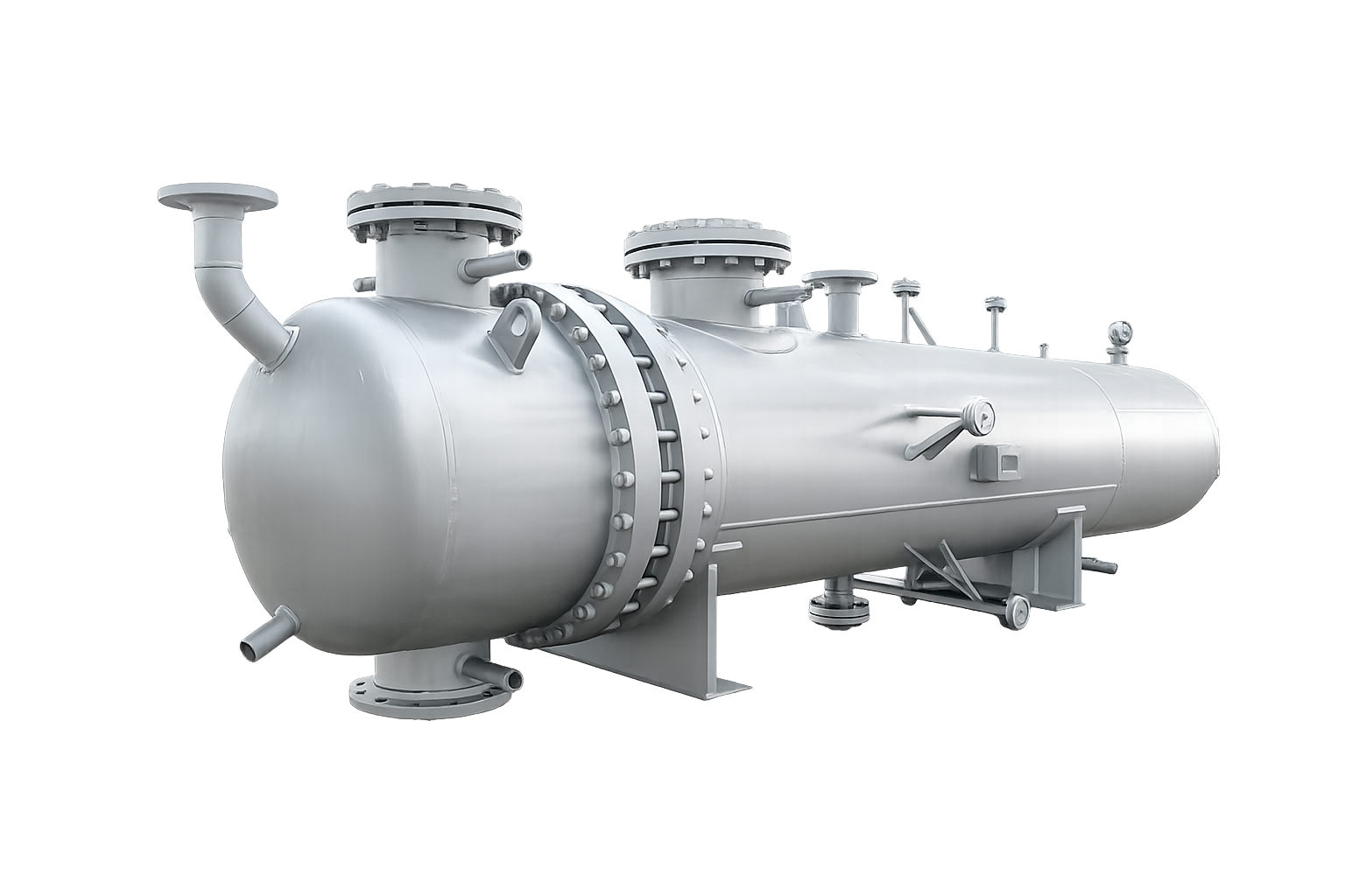 Heat Exchanger
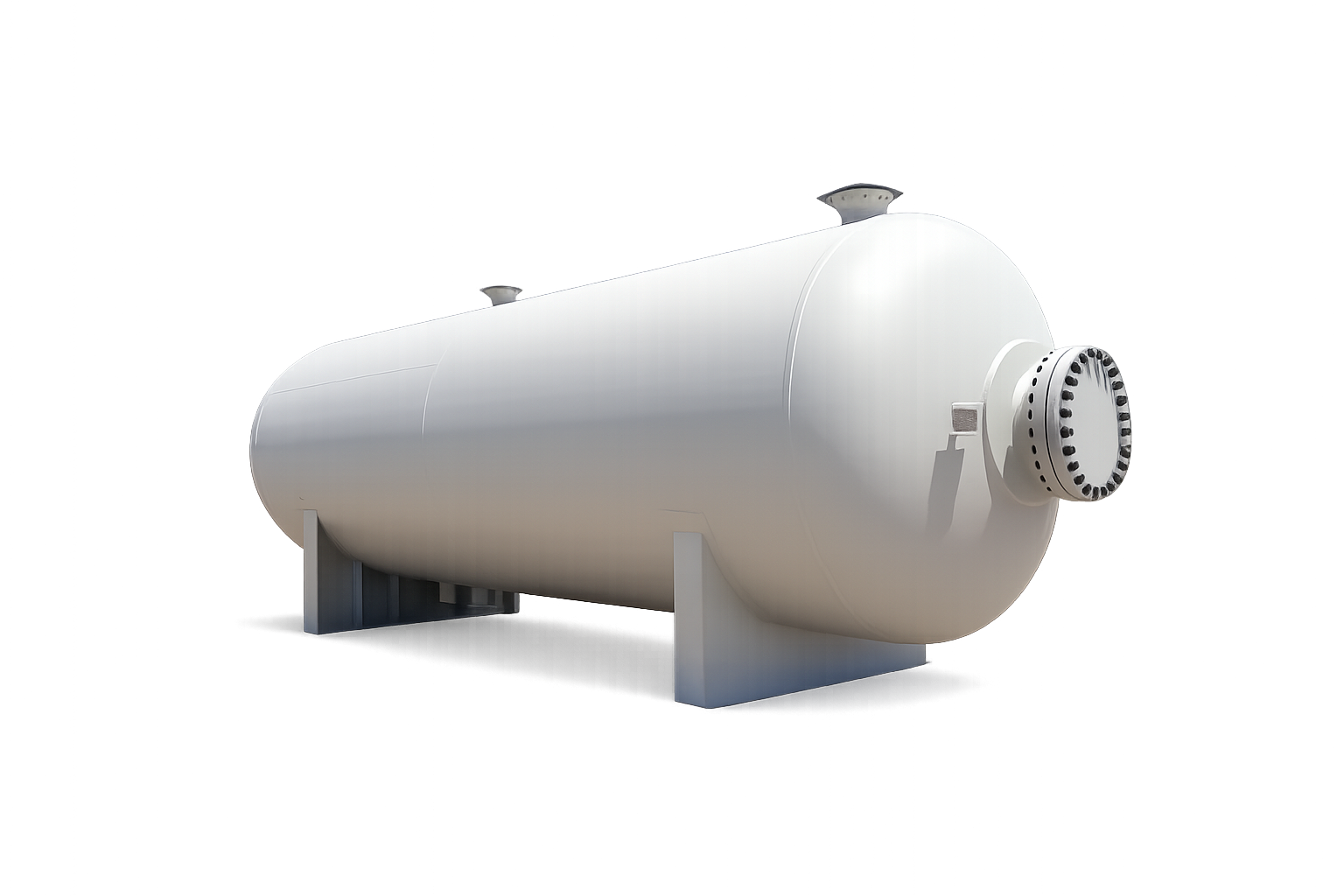 Pressure Vessel
 Silo
 Solvent Stripper
 Pharma Equipments