A design-focused guide to shell and tube heat exchangers: reading TEMA designations, fixed tubesheet vs floating head vs U-tube, tube layout and pitch, baffles, velocities, fouling, thermal expansion and what to put on the data sheet.
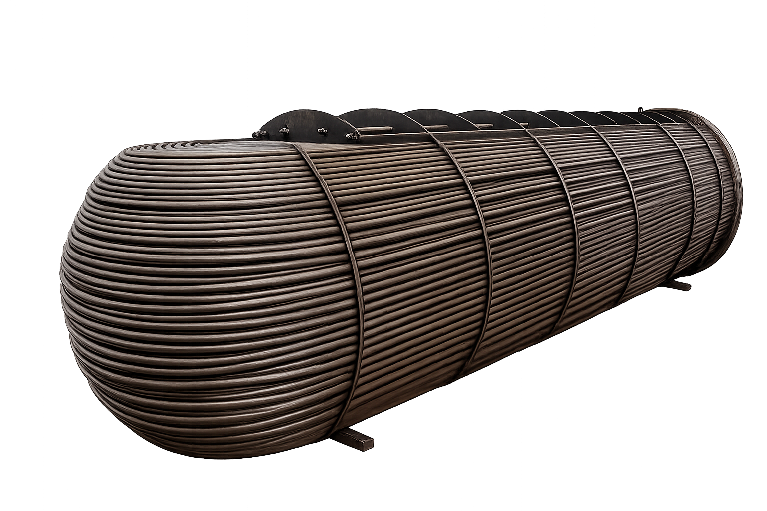
A shell and tube heat exchanger is designated by a three-letter TEMA code: front head type, shell type and rear head type, for example AES (removable channel, single-pass shell, floating head with backing device), BEM (bonnet, single-pass shell, fixed tubesheet) and AEU (U-tube). The type is chosen from the temperature difference, fouling and cleaning needs, and the class (R, C or B) from the service severity.
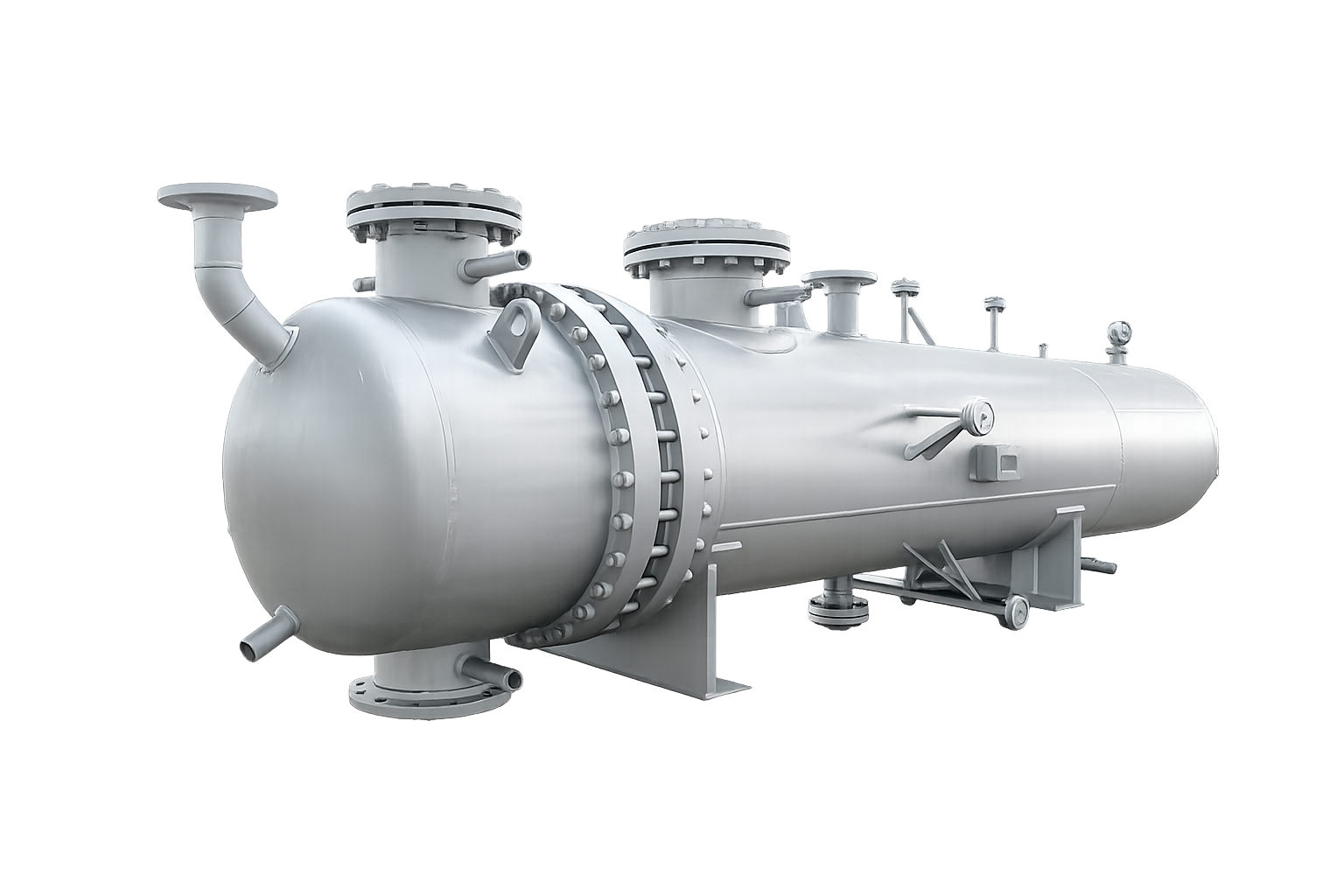
A shell and tube heat exchanger consists of a bundle of parallel tubes enclosed in a cylindrical shell. One fluid flows inside the tubes and the other flows through the shell around them. The tubes are held at each end in tubesheets, and baffles support the tubes and force the shell-side fluid to zig-zag across the bundle. Channels or bonnets at the ends distribute the tube-side fluid and, with partition plates, divide it into multiple passes. For the fundamentals, see our introduction what is a heat exchanger.
| Part | Role |
|---|---|
| Tube bundle | Heat transfer surface; tube diameter, thickness and length set area |
| Tubesheets | Hold tube ends and separate shell side from tube side |
| Baffles and tie rods | Support tubes, direct shell-side flow, resist vibration |
| Shell and nozzles | Contain the shell-side fluid |
| Front and rear heads | Distribute and collect tube-side fluid, give access |
| Expansion joint (if used) | Absorbs thermal expansion in fixed-tubesheet units |
| Supports (saddles) | Carry weight, allow for expansion |
TEMA names each exchanger with three letters. The first letter describes the front-end head, the second the shell, and the third the rear-end head. The most common letters are:
| Position | Letter | Meaning |
|---|---|---|
| Front head | A | Removable channel with removable cover |
| Front head | B | Bonnet (integral cover) |
| Shell | E | One-pass shell (the standard) |
| Shell | F | Two-pass shell with longitudinal baffle |
| Shell | K | Kettle-type reboiler shell |
| Shell | X | Cross-flow shell |
| Rear head | L | Fixed tubesheet, like A front head |
| Rear head | M | Fixed tubesheet, like B front head |
| Rear head | S | Floating head with backing device |
| Rear head | T | Pull-through floating head |
| Rear head | U | U-tube bundle |
Examples: AES is a removable channel, one-pass shell, floating head with backing device, and is a classic choice for fouling services where the bundle must be pulled for cleaning. BEM has a bonnet, one-pass shell and a fixed tubesheet with bonnet at the rear, and is simple and economical for clean services. AEU has a U-tube bundle, which expands freely. AKT or AKU are kettle reboilers (see reboiler guide).

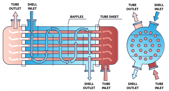
| Feature | Fixed tubesheet (BEM, AEL) | Floating head (AES, AET) | U-tube (AEU, BEU) |
|---|---|---|---|
| Thermal expansion | Limited; may need expansion joint | Free movement of floating head | Free movement of tubes |
| Shell-side cleaning | Chemical only (bundle cannot be pulled) | Mechanical cleaning possible with bundle removal | Bundle removable |
| Tube-side cleaning | Easy (straight tubes) | Easy | Difficult at the U bends |
| Cost | Lowest | Highest | Moderate |
| Best for | Clean shell-side fluids, small temperature difference | Fouling services, large temperature difference | Clean tube-side fluid, thermal cycling |
Tubes are arranged on a triangular (30 degrees), rotated triangular (60 degrees), square (90 degrees) or rotated square (45 degrees) pitch. A triangular layout packs more tubes in a given shell and gives higher shell-side heat transfer, but the lanes between tubes are too narrow for mechanical cleaning. A square layout leaves straight cleaning lanes and is preferred for fouling shell-side fluids. The tube pitch is usually about 1.25 times the tube outside diameter. Common tube outside diameters range from about 19 mm (3/4 inch) to 25 mm (1 inch), with wall thickness selected for pressure, corrosion allowance and tube material. Longer tubes give more area at lower cost, within limits of bundle handling and plant space.
Baffle spacing typically falls between about 0.2 and 1.0 times the shell inside diameter. Closer spacing raises velocity and heat transfer but also pressure drop and vibration risk. The right choice balances heat duty, allowable pressure drop and flow-induced vibration.
Higher fluid velocity raises the heat transfer coefficient and reduces fouling, but it also increases pressure drop and the risk of erosion and vibration. For water in tubes a typical design target is in the range of roughly 1 to 2.5 metres per second, though materials, fluids and allowable pressure drop will change this. Low velocities invite deposits of sludge and scale, so a design that meets duty on paper may foul quickly in service. The fouling factor in the design adds surface to allow for deposits, and the data sheet should state it for each fluid.
Pressure drop is part of the specification, not only the result. A pump or compressor limits how much you can spend on the exchanger, so state the allowable pressure drop on each side.
Tubes and shell expand differently when they are at different temperatures or made of different metals. In a fixed-tubesheet exchanger this difference stresses the tubesheet and tube joints, so large temperature differences call for an expansion joint, a floating head or a U-tube design. Mechanical design follows ASME Section VIII Div 1 for pressure parts and TEMA for tubesheet thickness, tolerances and construction. Tube-to-tubesheet joints may be expanded, seal-welded or both, depending on pressure, temperature and leak tolerance. Hydrostatic tests are performed on both shell and tube sides, with the bundle assembled and inspected.
Heat transfer area follows from the basic equation Q = U × A × LMTD, where Q is the duty, U the overall heat-transfer coefficient, A the area and LMTD the log-mean temperature difference. Suppose a process liquid is cooled from 100 °C to 60 °C by cooling water heated from 30 °C to 50 °C in counter-current flow.
This is a simplified illustration: real designs use a correction factor for multi-pass flow, detailed film coefficients on each side and a vendor design program. It shows why inlet and outlet temperatures, duty and an honest estimate of U drive the size of the exchanger.
Our quality system covers NDT by RT, UT, PT, MT and VT with full material traceability, and we supply a complete documentation dossier with each exchanger.
Class R is for the severe requirements of petroleum and related processing, Class C for moderate commercial and general process applications, and Class B for chemical process service. The classes differ in details such as minimum thickness, corrosion allowance and construction. Specify the class on your data sheet. Creative Engineering builds to TEMA classes B, C and R and supports IBR and IS 4503 requirements where applicable.
Send the data sheet through the contact page. For related equipment see box heat exchangers, the heat exchanger manufacturing page and reboilers.
AES is a TEMA code: A front head (removable channel), E shell (one pass) and S rear head (floating head with backing device). It is used where the bundle must be removable for cleaning and expansion is large.
BEM means bonnet front head, one-pass shell and bonnet fixed-tubesheet rear head. It is a simple, low-cost fixed-tubesheet design for clean services.
A heat exchanger whose tubes are bent in a U and fixed to a single tubesheet, so the bundle expands freely and is removable.
Typically the cleaner fluid, the fluid at lower pressure or the one with higher flow, depending on cleaning method; the corrosive or fouling fluid goes on the tube side in fixed-tubesheet units.
Single segmental baffles often have a cut around 20 to 25 percent of the shell diameter.
R is for severe petroleum duty, C for moderate commercial service and B for chemical process service.
Creative Engineering manufactures shell and tube, U-tube, hairpin and corrugated tube heat exchangers to TEMA and ASME Section VIII Div 1 in Ankleshwar, Gujarat.
Use Q = U x A x LMTD. Determine the duty Q, estimate the overall coefficient U and calculate the log-mean temperature difference, then add a margin for fouling and uncertainty.
Creative Engineering, Ankleshwar, Gujarat designs and manufactures process equipment to ASME and IBR codes. Share your drawing or process data and our team will respond with a technical offer.








 Reactor
 High Pressure Vessel
 Skid Equipment
 Receiver
 Heat Exchanger
 Pressure Vessel
 Silo
 Solvent Stripper
 Pharma Equipments